
Short answer
How do I read the symbols and dimensions on a house plan? A house plan uses standard symbols for windows, doors and fittings, and dimensions in millimetres, unless a note says otherwise. IS 962 sets these conventions. A window shows in the elevation and a door in the plan, and the point where two lines cross on a window shows the hinged side. Ask the architect to explain any symbol the plan does not show in its key.
On this page (9)
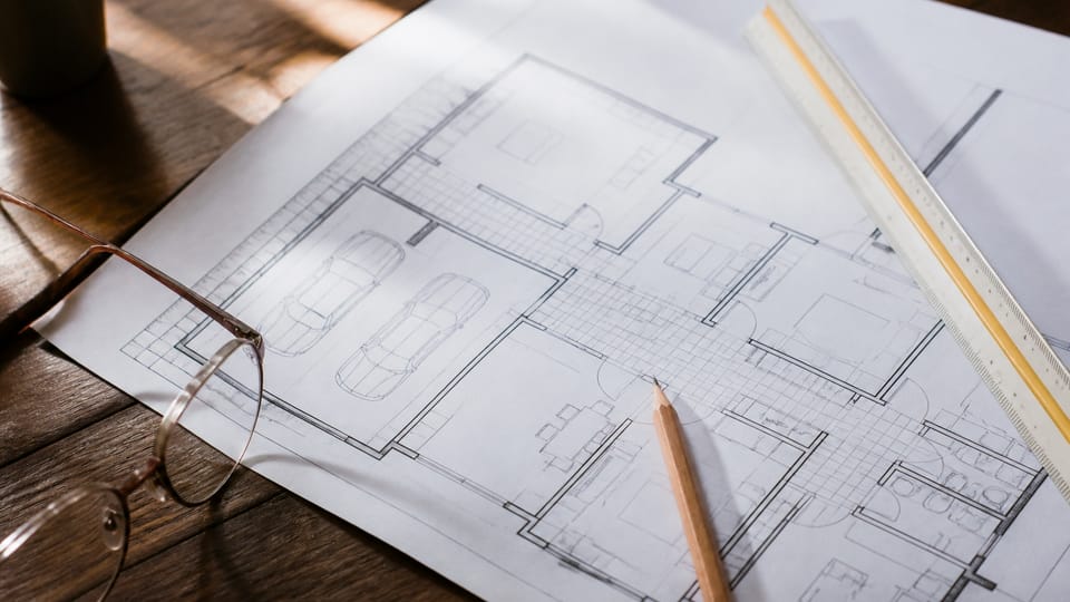
A house plan is a drawing, and it is read with a few rules. Dimensions give the size of each room and wall, symbols show the windows, doors and fittings, and a line shows where a wall is cut. This guide explains the common conventions in the Indian drawing code, IS 962, and what to check when the architect explains the plan. It does not give room sizes or wall thicknesses, which are in the plan itself and in the engineer’s drawings.
What units do the dimensions use?
IS 962 says that “Dimensioning shall be done normally in millimetres”. The symbol for the unit may be left out, but then “a prominent note is added stating the unit in which all the dimensions of the drawing are expressed” (clause 10.2.6). The standard says the unit symbol may be omitted only if a prominent note states the unit. Other units are shown with specific notations.
What do the dimensions measure from?
The standard gives two rules, one for each kind of structure. For a framed structure, “all dimensions should be related to the column or stanchion centres, which, in turn, are related to the building line” (clause 10.2.4). For a wall-bearing building, “dimensions should be related to the rough unfinished wall faces” (clause 10.2.5).
So a dimension on a framed plan is measured to the centre of a column, and on a wall-bearing plan to the rough face of the wall. Ask the architect which rule the plan uses, because the same room measures differently under each.
How are windows and doors shown?
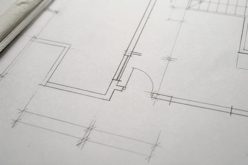
IS 962 says that “Generally, window openings shall be defined in elevation, and doors, screens and sliding windows on the plan” (clause 11.3). So a window is marked in the elevation, and a door is marked on the floor plan.
The standard also says that “The point or apex of two lines crossing the ventilator or casement indicates the hinged side” (clause 11.3). The apex of the crossing lines on a window symbol marks the hinged side.
What do the other symbols mean?
The standard says that symbols “are in constant use on small-scale drawings”, and that time is saved and confusion avoided when a standard set of symbols is used extensively (clause 11.1). Electrical symbols are given in the standard’s figure for installations (clause 11.4), and sanitary appliances and general fitments are shown by the standard’s recommended symbols (clause 11.6). The drawing’s own key is the reference for any symbol that differs.
What should I check on the plan?
This section is practice, not a code rule.
- The unit of the dimensions, and whether a note states it.
- Which structure the plan uses, framed or wall-bearing, and so which line the dimensions measure from.
- The window symbols in the elevation and the door symbols on the plan, with the hinge side marked.
- A key or legend for the symbols used, and any symbol the key does not explain.
- A sheet number and a revision record, so that you know you have the latest drawing.
What mistakes should I avoid?
This section is practice.
- Reading a dimension from the wrong line, because the plan measures to a different face than you assumed.
- Assuming a symbol means the same thing on every drawing, without checking the key.
- Building from an old sheet when the plan has a later revision.
- Missing a door swing, and finding it blocks a cupboard or a bed only after the walls are up.
- Taking a scale from memory and not measuring the printed dimension.
Frequently asked questions
Can I measure the room with a scale ruler?
You can check a plan with a scale ruler, but the printed dimension governs. The architect and the contractor work to the dimension, not to the scale.
Does the plan show the structure?
A house plan shows the layout and the walls. The structural drawings show the foundation, the beams, the columns and the slabs, and the engineer prepares them.
What if a symbol is not in the key?
Ask the architect to add it to the key and to explain it. Do not build to a symbol you have not understood.
Related guides
This guide is general information. Read the disclaimer. Your architect explains the plan for your house.
Sources
General information only. It is not a structural design or professional advice. Ask a licensed structural engineer or architect to check your plans and site.