
Short answer
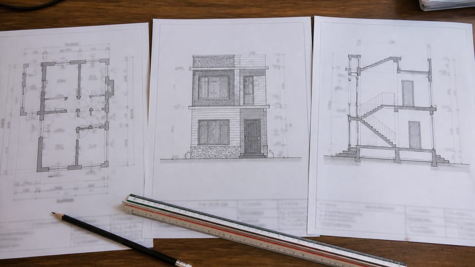
What is the difference between a floor plan, an elevation and a section? A plan is the view of a floor from above, an elevation is a view of an outside face of the building, and a section is a vertical cut through the building that shows heights. IS 962 names these views but does not define them. The Model Building Bye-Laws ask for all elevations and for a section through the staircase, kitchen, toilet and bath.
On this page (8)
A house drawing set has several kinds of sheet, and the three owners mix up most are the floor plan, the elevation and the section. They show the same building from three directions, and each answers different questions. The words are used loosely, and neither IS 962 nor the model bye-laws define them, so this page says what the words mean in common use (practice), what the standards say, and what to check in each view. It prints no scale, dimension or colour. For the other drawing types and the approval set, see working drawings for a house.
What does each view show?
In common use, these are the three views. The descriptions are practice, and the standards do not define them.
| View | What it is | What an owner reads from it |
|---|---|---|
| Floor plan | The view of one floor from above, with the walls and openings shown in outline | Rooms and their sizes, door and window positions, door swings, staircase position and width, the places of toilets and kitchen fittings |
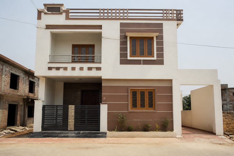
| Elevation | A view of one outside face of the building, looking straight at it | How the outside looks, where windows and doors sit on the wall, projections such as a chajja, the parapet and roof edge, floor levels and the plinth |
| Section | A vertical cut through the building, drawn as if the near part were removed | Heights: floor to floor, ceiling, sill, parapet, stair headroom, the roof slope, and what the footings and slabs are made of |
In practice a plan shows little height, an elevation shows no inside, and a section is where heights are usually read. That is why, in practice, a plan alone is not enough to build from, and why a pleasing elevation can hide a low ceiling.
What do the standards say?
IS 962:1989 does not define a plan, an elevation or a section. It names them in its projection clauses. Clause 8 describes first angle and third angle projection, in which the view from above, the view from below and the views from the left, right and rear are placed around the front view. Its Fig. 2 labels the view from above “PLAN” and the side views “ELEVATION A”, “ELEVATION B” and “ELEVATION D”. The standard does not say which of the two projection systems a house drawing must use. It says “window openings shall be defined in elevation, and doors, screens and sliding windows on the plan” (clause 11.3), which is why a window is read from the elevation and a door from the plan; see how to read a house plan: symbols and dimensions.
For sections, IS 962 gives the cutting plane its own line type, a thin chain line that is thick at the ends and where the cut changes direction (Table 5, line type H), and a clause on how materials are shown in section (13.1 and Table 7): brick and concrete have different symbols, and hatching or colour is used where confusion could arise. The standard does not say how a section is labelled on the plan, and it gives no height for a plan cut. Its abbreviations include ELEV for an elevation view, CS for a cross-section, RL for reduced level, FFL for finished floor level, GL for ground level, DPC for damp-proof course and NTS for not to scale (Table 6). Table 6 lists both ELEV (elevation as a view) and EL (elevation). The word also means a height: the model bye-laws define the road level as “the officially established elevation or grade of the centerline of street”, and on drawings EL is often used for a level such as a floor level (practice, not stated in the standard).
The model bye-laws (a model that applies only where adopted) say what the building plan holds (clause 2.10.5):
- The floor plans of all floors, with the sizes of rooms and the position and width of staircases, ramps and exit ways, and the exact location of the W.C., sink and bath (2.10.5(a) to (c)).
- A sectional drawing “showing clearly the sizes of the footings, thickness of basement wall, wall construction, size and spacing of framing members, floor slabs and roof slabs with their materials”. The section “shall indicate the heights of building and rooms and also the heights of the parapet and drainage and the slope of the roof. At least one section shall be taken through the staircase, kitchen and toilet, bath and W.C.” (2.10.5(d)).
- “Show all elevations” (2.10.5(e)). The model says no more about what an elevation must show.
- A terrace plan with the drainage and the slope of the roof, the north point, and the doors, windows and other openings with sizes in a schedule (2.10.5(h), (i), (k)).
So the standards agree with the common meaning on one point: the section is where the heights are. They leave the definitions to practice. The model bye-laws also set out scales by plot size and a table of sheet sizes (2.10.5, 2.9.5), and the local authority may change them and add its own particulars; this page prints none of them.
What should I check in each view?
This is practice, not a standard, unless a clause is named.
Plan.
- The rooms suit your needs, and your furniture fits the printed dimensions.
- Door positions and swings, and window positions, and that the openings are listed with their sizes in the schedule (MBBL 2.10.5(k) asks for the schedule).
- The staircase position and width, and the W.C., sink and bath (2.10.5(a), (c)).
- Where each section is cut: the plan marks the cut lines.
Elevation.
- All the elevations are there, not only the front (2.10.5(e)).
- The windows and doors on each wall match their places in the plan.
- The sill and lintel levels, the parapet, the roof edge and any chajja or projection.
- The ground line and the plinth level, which should match the sanctioned plan: see plinth height for a house: the level, the minimum and who sets it.
Section.
- The floor-to-floor and ceiling heights, and the sill height.
- The depth of the beams and slabs, so that a beam does not lower a ceiling below the height shown. In numbering storeys, IS 962 recommends marking the level between storey numbers at the upper face of the load-bearing floor element (clause 14.5.2, Fig 19); a finished floor level is above that. For the room-height rules in the model bye-laws, see room sizes, ceiling height and windows: what the model bye-laws say.
- The stair headroom, on the section through the staircase.
- The parapet, the drainage and the roof slope (2.10.5(d)); see parapet wall: purpose, the model bye-law height rule and coping.
- The plinth, the loft and the water tank heights, if they are shown.
Where do the three views disagree?
The most common mismatches are these. They are practice checks.
- A window shown in the plan is missing, or in a different place, in the elevation.
- A door or window height does not fit the lintel line in the section.
- A beam lowers the ceiling below the figure in the section.
- No section goes through the staircase, so the headroom is never shown.
- The plinth level or the parapet height differs between the elevation, the section and the sanctioned plan.
- A 3D render shows a balcony, a projection or a window that the 2D drawings do not.
- A window or door is changed on site and the drawings are not updated.
What mistakes should I avoid?
These are practice, not code rules.
- Approving the plan and never looking at the section.
- Trusting a 3D picture over the 2D drawings. The 3D picture is an extra, and it is not an elevation drawing.
- Asking for the front elevation only.
- Checking an elevation for looks and not for heights and levels.
- Asking for no section through the staircase, kitchen and toilet.
- Changing something on site without a revised drawing.
- Taking sizes from a scale ruler on a print instead of the printed dimensions.
Frequently asked questions
What is the difference between a floor plan and an elevation?
A floor plan shows a floor seen from above, with rooms and openings. An elevation shows one outside face seen straight on, with heights and the look of the walls.
What is a section drawing used for?
To show heights and construction: floor to floor, ceiling, parapet, stair headroom, roof slope and the footings and slabs. The model bye-laws ask for at least one section through the staircase, kitchen and toilet.
Is a 3D elevation the same as a 2D elevation?
No. A 3D picture is a view for appearance. Drawings for approval and construction are 2D plans, elevations and sections, and heights are read from the section.
Does IS 962 define a plan, an elevation and a section?
No. It uses the words in its projection clauses and labels, and gives a line type for the cutting plane, but it has no definitions.
How many elevations does a house need?
The model bye-laws say “all elevations”. IS 962 labels the sides of the plan A to D and does not name them front and rear.
Related guides
- Working drawings for a house: the full list to get before construction
- How to read a house plan: symbols and dimensions
- Building plan approval for a house: steps and documents
This guide is general information. Read the disclaimer. Your architect decides the drawings for your house and your local authority decides which of them it needs.
Sources
- IS 962:1989, Code of Practice for Architectural and Building Drawings (second revision): clauses 8.0 to 8.2 and Fig 2, 9.2 and Table 5, 12.1 and Table 6, 13.1 and Table 7, 14.5.2 and Figs 18 and 19 (page images read). BIS lists it as in force, valid to 2027-01-31. It does not define plan, elevation or section.
- Model Building Bye-Laws 2016 (Town and Country Planning Organisation, Ministry of Housing and Urban Affairs): clause 2.10.5(a) to (e), (h), (i) and (k) on the building plan (page images read). A model prepared for the guidance of States and urban local bodies; it applies only where adopted.
General information only. It is not a structural design or professional advice. Ask a licensed structural engineer or architect to check your plans and site.