
Short answer
What should an electrical layout drawing for a house show? NBCS 2026 clause 6.4 says the electrical layout should be drawn, showing every outlet and the best route for wiring, with all runs and points marked on the plans and cleared by the Engineer-in-Charge or the owner before work starts. It gives no template. A completion wiring diagram with every point and circuit number is handed over at the end.
On this page (9)
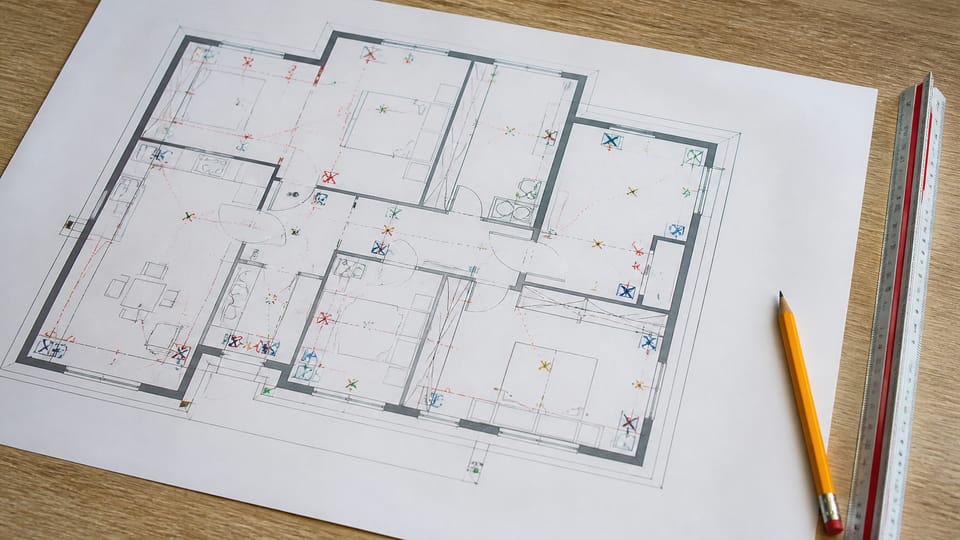
Most electrical problems in a new house are decided before a single wire is pulled: where each light, fan, switch and socket goes, where the distribution board sits, and what is planned for the air conditioner and the geyser. A point that is missing or in the wrong place is cheap to fix on paper and costly to fix after the plaster. The Indian codes say what the drawing is for, but they give no template for it. This page sets out what they say, what they leave out, and a checklist of what an owner can ask the drawing to show. It gives no circuit size, no wire size, no breaker rating and no height. For the wiring stages, see electrical work in a house build: stages and inspection points.
What does the code say about the drawing?
| Source | What it says |
|---|---|
| NBCS 2026 Part D Sec 2, clause 4.1.3 | Coordination among the architect, civil engineer, electrical engineer and mechanical engineer “shall be ensured from the planning stage of the installation”. Where required, prior approval of drawings is taken from the electrical supplier or inspector |
| NBCS clause 6.4.1 | “The electrical layout should be drawn indicating properly the locations of all outlets, such as lamps, fans, appliances (both fixed and movable), and motors and best route for wiring” |
| NBCS clause 6.4.2 | All runs of wiring and the exact positions of all points of switch-boxes and other outlets “shall be first marked on the plans of the building”, and then cleared by the Engineer-in-Charge or the owner before the work actually starts |
| NBCS clause 3.5.2 | Where an electrical consultant is appointed, the consultant is responsible for preparing designs with drawings and specifications, including drawings of the internal routes and layouts of cables and the points and distribution boards. The contractor builds to that design (clause 3.5.3) |
| NBCS clause 4.1.4 | While planning the wiring, information “should be exchanged” between the owner, architect, consultant, electrical contractor and the supply authority, including the space needed for meters and switches and the total load of lights, fans and power, with allowance for the expected growth in use |
| NBCS clause 4.1.5 | Adequate provision should be made for all services needed “immediately and during the intended useful life of the building”, so that users are not tempted to extend the installation themselves or rely on multi-plug adaptors and long flexible cords |
| IS 4648:1968 clauses 3.1 to 3.3 | The same exchange of information before wiring. For a conduit wiring system, the work “should start before finishing work like plastering has begun” |
| IS 732:2019 clause 4.1.3.3 | The number and type of circuits are determined by the location of points of power demand, the loads expected on the circuits and the anticipated future demand “if specified” |
| IS 732 clause 5.1.4.5.1 | “Where appropriate”, diagrams, charts or tables show the type and composition of circuits, and the devices that protect, isolate and switch them and where they are. “For simple installations” this may be a schedule |
| IS 732 clause 4.1.3.13 | Every installation shall have “appropriate documentation” |
| NBCS clause 9.1.5 | On completion, a wiring diagram is prepared and submitted to the Engineer-in-Charge or the owner (details below) |
| Model Building Bye-Laws 2016, clause 2.10.7(a) | “Details of building services, where required by the Authority” are made available to a scale not less than 1:100. The longer services list in clause 2.10.6, which includes electrical services, is for buildings above 4 storeys or 15 m and special buildings. The bye-laws are a model, adopted state by state |
So NBCS says the layout should be drawn, with the points marked on the plans and cleared before work starts, but it gives no template or format, and we found nothing that says a small house must hire a consultant. IS 4648 is titled a guide and is a 1968 text, though NBCS 5.11 refers to it for the electrical layout of residential buildings.
What does the completion diagram have to show?
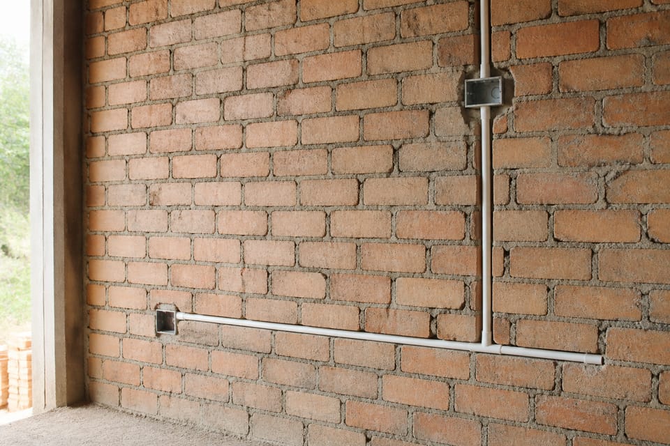
NBCS clause 9.1.5 is the most specific text. On completion, a wiring diagram “shall indicate clearly the main switch board, the runs of various mains and submains cables and the position of all points and their controls”. All circuits are to be “clearly indicated and numbered”, and every point is given the same number as the circuit it is connected to. The location and number of earth points are to be shown. NBCS 9.2.2.4(k) asks for clear and permanent identification marks painted on distribution boards, switch boards and switches as necessary. IS 732 clause 6.2.4 asks for an initial report with records of inspections and of the circuits tested, identifying every circuit and its protective device, given to the person who ordered the work. For the protection devices and earthing themselves, see MCB vs RCCB vs RCBO: what each protects against at home and earthing for a house: what it is, earth vs neutral, and why it matters.
Three kinds of electrical drawing (practice)
The words are used loosely. This is practice, not a standard definition.
- Layout drawing: a plan of each floor showing where each point, switch, socket, the distribution board and the meter go, with the conduit routes at a general level.
- Wiring or circuit diagram: how the circuits connect, and which points belong to which circuit. NBCS Fig. 3 is a wiring diagram for a typical distribution scheme in a residential flat.
- Single-line diagram: the power path in one line each: the meter, the main switch, the earthing, the protection devices and the circuits.
What should the layout show? (practice)
An owner-level checklist. The codes give no complete list: NBCS 6.4.1 asks for the outlets, appliances and wiring route, and IS 4648 clause 9.8 recommends socket counts by room (not printed here, as it is a 1968 table). The rest is practice.
- The scale, the north and a legend that explains every symbol. NBCS clause 2.2 says the symbols used in drawings and wiring plans for electrical installations in buildings shall be as given in its Annex A. IS 962 clause 11.4 also gives electrical symbols (Fig. 9) and clause 11.2 asks for the symbols to be drawn to scale where practicable. IS 732 clause 5.1.4.5.2 points to the IS 12032 series, which BIS now lists as withdrawn, so ask the electrician which symbol set is used.
- In each room: lights, fans, switches, sockets and the fan regulator, drawn against the furniture and the door swing.
- Points for the air conditioner, geyser, fridge, kitchen appliances, TV and data, the bell, and the outdoor and gate lights.
- The meter and the distribution board, and the provision for an inverter, solar or a future load.
- The earthing and the main routes of the conduit, in the slab or in the wall chases.
- A date, a version and the names of who drew it and who approved it.
How is it made, and who checks it?
NBCS 3.5.2 puts the design and drawings with the electrical consultant, and 6.4.2 has the points marked on the plans and cleared by the Engineer-in-Charge or the owner before work starts. In practice the drawing is made from the architect’s plan, the furniture layout, the appliance list and a talk with the owner: who sleeps where, where the TV goes, which rooms will have an air conditioner. An electrician, an electrical designer or an engineer prepares it, and the owner signs it off. Walk each room on paper with the furniture drawn in, and stand in the room against the bed, the sofa and the kitchen counter. Check each switch against the door swing. Do it before the conduit goes into the slab and the walls, and before plastering. Mark the positions on the wall before any chase is cut, keep a copy, photograph the conduit and the boxes before they are covered, and ask for the completion diagram and the test report at handover.
What mistakes should I avoid? (practice)
- No drawing, so the electrician decides each point on the day.
- A drawing made without the furniture layout.
- No legend, no scale and no date.
- No provision for the air conditioner, geyser, inverter, solar or a future load.
- A drawing that is not updated when the plan changes.
- No photos of the conduit before plaster, and no completion diagram.
- Treating a sample wiring diagram from the internet as your drawing. A sample is a format; it does not know your plan.
- Confusing the layout drawing with the circuit diagram.
Frequently asked questions
Is an electrical layout drawing compulsory for a house?
NBCS 2026 clause 6.4 says the layout should be drawn and the runs and points marked on the plans before work starts, and clause 9.1.5 asks for a completion wiring diagram. It gives no template. The model bye-laws ask for building services details where the Authority requires them.
What is the difference between a layout and a wiring diagram?
A layout shows where points and boards go on the plan. A wiring diagram shows how the circuits connect. This is practice usage.
Who makes the electrical drawing?
NBCS 3.5.2 puts the design and drawings with the electrical consultant where one is appointed. For a small house, in practice an electrician, an electrical designer or an engineer makes it, and the owner signs it off.
What should I get at the end?
NBCS clause 9.1.5 says a completion wiring diagram is submitted to the Engineer-in-Charge or the owner, with the main switch board, cable runs, every point and its circuit number, and the earth points. NBCS 9.1.6 asks for test reports.
Can I use a sample wiring diagram from the internet?
Only as a format. It does not know your plan, your loads or your furniture.
Related guides
- Electrical work in a house build: stages and inspection points
- Working drawings for a house: the full list to get before construction
- How to read a house plan: symbols and dimensions
- kW vs kVA vs kWh: what each unit means on a meter, inverter and bill
This guide is general information. Read the disclaimer. Your electrician and engineer decide the electrical design of your house.
Sources
- SP 7:2026, National Building Construction Standards (NBCS) 2026, Part D Section 2, Electrical and Allied Installations: clauses 2.2 and Annex A (symbols), 3.5.2, 4.1.3 to 4.1.5, 5.11 and Fig. 3, 6.4, 9.1.5, 9.1.6 and 9.2.2.4(k) (page images read, except 3.5.2 and Annex A: text layer). From an unofficial archive.org copy.
- IS 732:2019, Electrical Wiring Installations, Code of Practice (fourth revision): clauses 4.1.3.3, 4.1.3.13, 5.1.4.1 to 5.1.4.5 and 6.2.4 (page images read). BIS lists it as in force, valid to 2029-12-31.
- IS 4648:1968, Guide for Electrical Layout in Residential Buildings: clauses 3.1 to 3.3 and 9.8 (page images read). BIS lists it as in force, valid to 2030-06-30. It is a 1968 text.
- IS 962:1989, Code of Practice for Architectural and Building Drawings (second revision): clauses 11.2 and 11.4 (page image read). BIS lists it as in force, valid to 2027-01-31.
- Model Building Bye-Laws 2016 (Town and Country Planning Organisation, as published on the MoHUA site): clauses 2.10.6 and 2.10.7(a) (page image read). A model: it applies only where a state or city has adopted it.
Change log
- : Added Related guides link to newly published article(s): kw-vs-kva-vs-kwh-what-each-unit-means-on-a-meter-an-inverter-and-a-bill. No other text changed. Approved by the reviewing engineer.
General information only. It is not a structural design or professional advice. Ask a licensed structural engineer or architect to check your plans and site.